ISSN 1884-0760
GRACE TECHNICAL REPORTS
Proceedings of the 1st Asian Conference on
Pattern Languages of Programs
(AsianPLoP 2010)
Volume I
Hironori WASHIZAKI Nobukazu YOSHIOKA
(editors)
GRACE-TR-2010-01
March 16, 2010
CENTER FOR GLOBAL RESEARCH IN
ADVANCED SOFTWARE SCIENCE AND ENGINEERING
NATIONAL INSTITUTE OF INFORMATICS
2-1-2 HITOTSUBASHI, CHIYODA-KU, TOKYO, JAPAN
Proceedings
AsianPLoP 2010
1st Asian Conference on Pattern
Languages of Programs
Volume I
Tokyo, Japan, March 16-17, 2010, Co-located with
The GRACE International Symposium on Advanced Software Engineering
Edited by
Hironori Washizaki and Nobukazu Yoshioka
Sponsored by
GRACE Center of the National Institute of Informatics (NII)
IPSJ/SIGSE Patterns Working Group
ACM Japan Chapter
Supported by
eXtreme Programming Japan Users Group (XPJUG)
AsianPLoP is a PLoP® Conference sanctioned by the Hillside Group.
Conference Committee
Conference Chair
Eiichi Hanyuda, Mamezou, Co. Ltd.
Program Co-Chairs
Hironori Washizaki, Waseda University / National Institute of Informatics GRACE Center
Nobukazu Yoshioka, National Institute of Informatics
Program Committee
Eduardo B. Fernandez, Florida Atlantic
University
Joseph W. Yoder, The Refactory Inc and
Joe Yoder Enterprises
Norihiro Yoshida, Osaka University
Masao Tomono, KameNet Inc.
Koido Ryo, eXtreme Programming
Japan User's Groups
Terunobu 'Terry' Fujino, InArcadia, Ltd.
Kiminobu Kodama, Information System
Research Institute
Kenji Hiranabe, Eiwa System
Management, Inc.
Masaru Amano, Eiwa System
Management, Inc.
Takeshi Kakeda, Eiwa System
Management, Inc.
Kenichiroh Ohta, IBM Japan
Yuriko Sawatani, IBM Japan
Akira Sakakibara, IBM Japan
Takao Okubo, Fujitsu Limited, Japan
Okita Naoyuki, Yokogawa Electric
Corporation
Akio Kawai, Object Design Laboratory,
Inc.
Yann-Gaël Guéhéneuc, Canada Research
Chair on Software Patterns and Patterns
of Software, École Polytechnique de
Montréal
Yuji Yamano, OGIS International, Inc.
Yoichi Hasegawa, Technoport
Takashi Iba, Keio University
Takashi Kobayashi, Nagoya University
Dinesha K V, IIIT Bangalore
Raj Datta, MindTree Ltd.
Eric Platon, Cirius Technologies
Foutse Khomh, DIRO, Universite de
Montreal, QC
Message from PC Co-Chairs
Welcome to the 1st Asian Conference on Pattern Languages of Programs, AsianPLoP
2010. AsianPLoP takes place at the first time, as a premier event for pattern authors
and users to gather, discuss and learn more about patterns and software development
in the Asia region as well as other regions.
The purpose of AsianPLoP is to promote development of patterns, pattern languages,
technologies and experiences of patterns primarily about software; however, these for
domains outside software are also welcome.
In AsianPLoP 2010, various patterns, pattern languages and related techniques will
be discussed. Topics include software design, services, security, interaction, pedagogy
and organizational change. Most of papers will be workshopped in the traditional
PLoP Writer's Workshop format. We received 16 paper submissions. After the
rigorous shepherding processes, 13 papers have been accepted for Writer’s Workshops
and 3 papers for Writing Groups. Moreover the 1st program incorporates one invited
talk and one tutorial.
We thank program committee members. They reviewed and conducted shepherding
processes for papers carefully and fairly. Moreover we thank our sponsors, supporters
and the Hillside Group for their kind supports. We hope that the 1
stconference of
AsianPLoP is successful, and will contribute the development of this filed.
Hironori Washizaki and Nobukazu Yoshioka
Invited Talk
Title: A Timeless Way Of Communicating
Presenter: Joshua Kerievsky (Industrial Logic, Inc.)
Abstract
If you pick up the masterpiece, "A Pattern Language", by Christopher Alexander et. al,
you will discover a book filled with engaging photographs, hand-drawn sketches, big
bold, hard-to-miss text, memorable stories and scholarly notes for the academically
minded. One can quickly "surf" this book by focusing only on pattern titles, images
and headlines or one can dive deep into the book by reading the detailed text of each
pattern. In short, A Pattern Language uses a timeless way of communicating, a form
that engages people and provides numerous pathways for accessing the knowledge.
As authors of software-related pattern languages, we must understand what it takes
to make our own works endure. In this talk, we will analyze the form and content of
real-world software patterns/pattern languages, looking for what makes them
succeed or fail at engaging the reader and providing knowledge pathways. If you are
interested in crafting great pattern languages, this talk will help you discover some
essential ingredients.
Biography
Tutorial
Title: Pattern Writing: The Straight Scoop
Presenter: Joseph W. Yoder (The Refactory, Inc.)
Abstract
Contents: Volume I
WW-1E: Security and Design
A pattern for the WS-Trust standard for web services ……….I-9
Ola Ajaj and Eduardo B. Fernandez (Florida Atlantic University)
A Worm misuse pattern ……….I-21
Eduardo B. Fernandez (Florida Atlantic University), Nobukazu Yoshioka (National
Institute of Informatics) and Hironori Washizaki (Waseda University)
Design Decision Topology Model for Pattern Relationship Analysis ………...I-31
Kiran Kumar Vajja and Prabhakar TV (Indian Institute of Technology Kanpur)
WW-2E Pedagogy and Organization
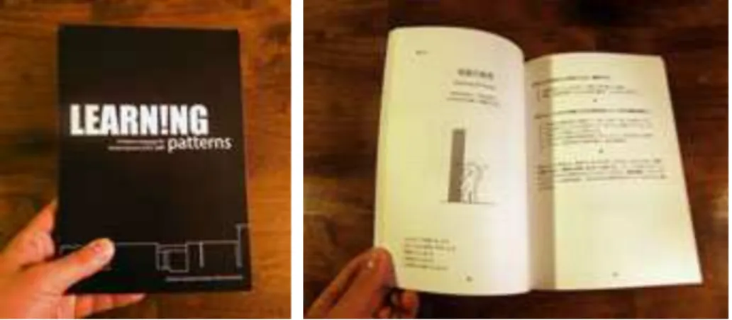
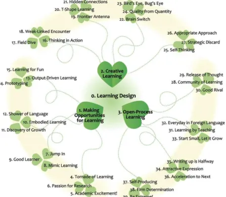
Learning Patterns: A Pattern Language for Creative Learners II ………...I-41
Takashi Iba (Keio University / MIT) and Toko Miyake (Keio University)
Metamorphosis - A Successful Organizational Change Management Pattern ……..I-59
Madhup Jain, Ranjith Kutty and Raju Dani (MindTree Limited)
WW-3E: Human Computer Interaction
Analyzing the HCI Design Pattern Variety ………...I-85
Christian Kruschitz and Martin Hitz (University of Klagenfurt)
WG-1E: Organization and Services
Research Organization Servicelization Patterns ……….I-95
Yuriko Sawatani (IBM Research-Tokyo)
WG-2E: Network Systems
Contents: Volume II
WW-1J: Quality and Pattern Language (in Japanese)
A Search for a Process getting “Quality” ……….II-9
Hiroshi Nakano and Bankoku Sasagawa (Center for Environmental Structure)
A Pattern Language for Environmental Design ……….II-53
Mizuki Oka (The University of Tokyo), Myeong-Hee Lee (Design Team Matt),
Yasuhiro Hashimoto (The University of Tokyo) and Kouichirou Eto (National
Institute of Advanced Industrial Science And Technology)
A Pattern Language for Organizing Events ………II-63
Kouichirou Eto (National Institute of Advanced Industrial Science and Technology)
and Shinobu Shibamura (WikiBana)
WW-2J Facilitation and Retrospective (in Japanese)
A Pattern Language for MIKOSHI and YORIAI ………II-75
Masanari Motohashi
A Pattern Language for Retrospective – Facilitator ………..II-89
Takeshi Kakeda (Eiwa System Management, Inc.)
WW-3J: Information Systems (in Japanese)
Towards A Pattern Language for Information Systems ………..II-101
Kiminobu Kodama (Information Systems Institute, Ltd.)
WW-4J: Business Processes (in Japanese)
Declarative Description of Business Process Patterns ………II-109
Tsukasa Takemura (NSD Co.,Ltd.)
WG-1J: Testing (in Japanese)
A pattern for the WS-Trust standard for web services
Ola Ajaj and Eduardo B. Fernandez
Department of Computer and Electrical Engineering and Computer Science
Florida Atlantic University
777 Glades Road, Boca Raton, Florida 33431-0991 USA
[email protected], [email protected]
Abstract
:
Web services intend to provide an application integration technology that can be successfully used over the Internet in a secure, interoperable and trusted manner. One of the main functionalities of web services is providing secure messaging, where the web services exchange security credentials (either directly or indirectly). However, each party needs to determine if they can trust the asserted credentials of the other party. Moreover, the dynamic interaction between the web services requires specifying trust relationships in an explicit way for all parties. Without a clear definition of how web services could manage secure communications and establish trust relationships with other partners, malicious web services could use their business interactions to perform illegal actions. The WS-Trust standard defines how to establish trust between interacting parties; we present here a pattern for this standard. WS-Trust defines a security token service and a trust engine which are used by web services to authenticate other web services. Using the functions defined in WS-Trust, applications can engage in secure communication after establishing trust.1. Introduction
Without a clear definition of how web services can manage secure communications and establish
trust relationships with other partners, it would be hard to perform any kind of interaction. WS-Trust is a
standard to support the establishment of trust relationships.
Using web services requires that we exchange credentials to define the rights of each participant.
This exchange is based on trust and builds further trust. Trust is based on security and other policies to
enable requesting and obtaining credentials within different trust domains. Both parties need to
determine if they can "trust" the asserted credentials of the other party. The goal of the WS-Trust
standard is to enable applications to construct trusted message exchanges. This trust is realized through
the exchange and brokering of security tokens [oas09].
The motivation toward WS-Trust is supported by the fact that there are different formats for
security tokens (e.g. X.509 certificates, Kerberos tickets, SAML assertions, XACML policies, etc.), and
it’s unlikely to expect that an endpoint will understand each of these options. Additionally, there is no
guarantee that there will be an intersection between the sets of supported security token formats of
different actors who are willing to exchange messages using the WS-Security standard [Mad03].
patterns to describe SAML, XACML, WS-Policy, WS-Security, XML Encryption, XML Digital
Signature, and others. A standard defines a generic architecture and this is a basic feature of any pattern;
it can then be confirmed as a best practice by looking at products that implement the standard (and
implicitly the pattern).
Section 2 shows a pattern that describes this standard. Section 3 ends the paper with some
conclusions.
2. A Pattern for WS-Trust
Intent
WS-Trust defines a security token service and a trust engine which are used by web services to
authenticate other web services. Using the functions defined in WS-Trust, applications can engage in
secure communication after establishing trust.
Example
The
Ajiad
travel agency offers its travel services through several different business portals to
provide travel tickets, hotel and car rental services to its customers.
Ajiad
needs to establish trust
relationships with its partners through these portals.
The
Ajiad
supports different business relationships and needs to be able to determine which
travel services to invoke for which customer. Without a well-defined structure,
Ajiad
will not be able to
know if a partner is trusted or not, or to automate the trust relationships quickly and securely with its
partners, which may lead to losing a valuable business goal of offering integrated travel services as a
part of the customer’s portal environment.
Context
Distributed applications need to establish secure and trusted relationships between them to
perform some work in a web-service environment which may be unreliable and/or insecure (e.g. the
Internet). The concept of "Trusting A" mainly means "considering true the assertions made by A", which
does not necessarily correspond to the intuitive idea of trust in its colloquial use.
WS-Security begins with the assumption that, if one of the parties uses a particular type of
security token within the WS-Security header, then the other party will be able to interpret and process
this token. A fundamental issue that WS-Security did not address is how two entities (a SOAP client and
SOAP Service) can agree on the nature and characteristics of the security tokens that are the
fundamentals of WS-Security.
Establishing security relationships is fundamental for the interoperation of distributed systems.
Without applying relevant trust relationships expressed in the same way between the involved parties,
web services have no means to assure security and interoperability in their integration. How can we
define a way for the parties to trust each other’s security credentials?
The possible solution is constrained by the following forces:
•
•
•
•
Knowledge:
In human relationships, we are concerned with first knowing a person before we
trust her. That attitude applies also to web services. We need to have a structure that encapsulates
some knowledge about the unit we intend to trust.
•
•
•
•
Policy consideration
:
The web service policy contains all the required assertions and conditions
that should be met to use that web service. The trust structure should consider this policy for
verification purposes.
•
•
•
•
Confidentiality and Integrity
:
Policies may include sensitive information. Malicious consumers
may acquire sensitive information, fingerprint the service and infer service vulnerabilities. This
implies that the policy itself should be protected.
•
•
•
•
Message integrity
: The data to be transferred between the partners through messages may be
private data that need to be protected. Attackers may try to modify or replace these messages.
•
•
•
•
Time Validity
: For protection purposes, any interactions or means of communications (including
the trust relationships) between the web services should have a time limit, that determines for
how long the trust relationship is valid.
Solution
We define explicitly an artifact (security token) that implies trust. This artifact implies what
kinds of assertions are required to make trustworthy interactions between the involved web services.
We should verify the claims and information sent by the requester in order to obtain the required
security token that becomes a proof enough to establish a trust relationship with its target partners.
Structure
Figure 1 describes the structure of this pattern.
Claim
is a statement made about the attributes of
a client, service or other resource (e.g. name, identity, key, group, privilege, capability, etc.). Claims are
assertions, for example: “I am Joman”, “I am an authenticated user and I am authorized to print in
printer P”. Claims are used to validate the requests made by a sender and need to be verified.
Token
that contains a secret
data
parameter that can be used to prove authorized use of an associated
security token and provides the function of adding digital signature. Usually, the proof-of-possession
information is encrypted with a key known only to the recipient of the PoP token.
The
Security
Token
Service (STS)
is a web service that issues security tokens. It makes
decisions based on evidence that it trusts. The
STS
is responsible for generating security tokens and,
providing challenges for the requester to ensure message freshness (the message has not been replayed
and is currently valid), verification of authorized use of a security token, and finally establishing,
extending and removing trust in a domain of services. The
STS
is the heart of WS-Trust and forms the
basis of trust brokering. The main output of the
STS
is a trust relationship between the requester and the
receiver expressed as a security token. It represents the characteristic that one entity is willing to rely
upon a second entity to execute a set of actions and/or to make set of assertions about a set of subjects
and/or scopes in a secure, reliable and time-relevant manner.
Each
STS
has a
Trust
Engine
that evaluates the security-related aspects of a message using
security mechanisms and includes policies to verify the requester’s assertions. The
Trust Engine
is
responsible for verifying security tokens and verifying claims against policies. A
Policy
is a collection
of policy assertions that have their own name, references, and ID. Policies form the basic conditions to
establish a trust relationship. Verifying the requester’s claims against policy assertions generates an
approval to use the target service. A policy may reference another policy (ies), in order to check the
tokens sent by the requester or verified by the receiver.
Dynamics
We describe the dynamic aspects of the WS-Trust using sequence diagrams for the use cases
“
create security token
” and “
access a resource using a token
”.
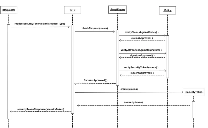
Create a security token (Figure 2):
Summary: STS creates a security token using the claims provided by the requester.
Actors: A Requester
Precondition: The STS has the required policy to verify the requester claims and the requester
provides parameters in form of
claims
and
RequestType
signed by a
signature
.
Description:
a.
The requester requests a security token by sending the required
claims
and
RequestType
signed
by a
Signature
to the STS. The signature verifies that the request is legitimate.
b.
The STS contacts the Trust Engine to check the requester’s claims.
c.
The Trust Engine contacts the web service’s policy to verify the claims including attributes
and security token issuers of the requester.
d.
Once approved, the STS creates a security token containing the requested claims.
e.
The STS sends back its
SecurityTokenResponse
with a security token issued for the requester.
Figure 1: Class Diagram for the WS-Trust Pattern
+generateStatments() -parameters Claim SignedSecurityToken +addDigitalSignature() -data ProofofPossession +addSignature() SecurityToken +generateAProof() -name -ID -reference Policy +verifyClaimsAgainstPolicy() +verifyAttributesAgainstSignature() +verifySecurityTokenIssuers() TrustEngine +generateSecurityToken() +renewSecurityToken() +validateSecurityToken() +cancelSecurityToken() +provideChallenge() +establishTrust() +extendTrust() +bootstratpTrust() SecurityTokenService_STS Requester Receiver * 1 * 1STS is a web service 1 1 requestToken 1 1 validateToken Cryptographically endorsed by a specific authoriy (X.509 or Kerberos ticket)
encrypted with a key known only to the recipient
Figure 2: Sequence Diagram creating a security token
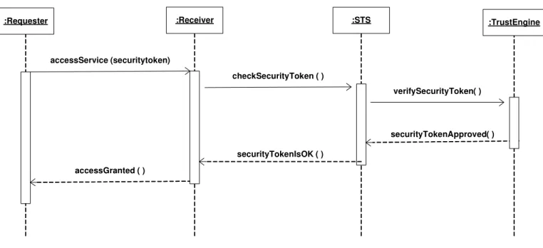
Access a resource using a token (Figure 3):
Summary: A STS allows the use of resources by establishing trust by verifying
proofOfClaims
sent
by the requester.
Actors: A Requester
Precondition: The Trust Engine has the required policy to verify the requester’ security token.
Description:
a.
The requester asks for a service access by providing the required security token.
b.
The receiver sends the security token to the STS for verification.
c.
The STS use its Trust engine to verify the security token claims.
d.
Once approved, the STS notifies the receiver that the security token is valid and verified.
e.
The receiver gives the requester a token that implies the right to use the service.
Postcondition: The requester has a security token that can be used to access services in a Receiver
web service.
:Requester :STS
claimsApproved( )
securityTokenResponse(securityToken)
:Policy
verifyClaimsAgainstPolicy( )
signatureApproved( ) :TrustEngine
checkRequest(claims)
issuersApproved ( ) verifySecurityTokenIssuers( )
RequestApproved( )
verifyAttributesAgainstSignature( ) requestSecurityToken(claims,requestType)
:SecurityToken create (claims)
Figure 3: Sequence Diagram accessing a resource using a token
Implementation
In this solution, the concept of trust is realized by obtaining a security token from the web
service (in our diagram, the Security Token Service) and submitting it to the receiver who in turn
validates that security token through the same web service. Upon approval, the receiver establishes a
valid trust relationship with the receiver that lasts as long as the security token is valid.
In order to assure effective implementation, we need to take in consideration the following:
•
To communicate trust, a service requires proof, such as a signature to prove knowledge of a
security token or set of security tokens. A service itself can generate tokens or it can rely on a
separate STS to issue a security token with its own trust statement.
•
Although the messages exchanged between the involved entities are protected by WS-Security;
still three issues related to security tokens are possible: security token format incompatibility,
security token trust, and namespace differences. The WS-Trust pattern addresses these issues by
defining a request/response protocol (in which the client sends
RequestSecurityToken
and
receives
RequestSecurityTokenResponse)
and
introducing a Security Token Service (STS) which
is another web service.
•
Based on the credential provided by the requester, there are different aspects of requesting a
security token (RST), each of which has a unique format that the requester should follow:
:Receiver :STS
securityTokenIsOK ( ) checkSecurityToken ( )
verifySecurityToken( )
securityTokenApproved( ) :Requester
accessService (securitytoken)
:TrustEngine
o
The issuance process: formed as
RequestSecurityToken (RequestType, Claims).
This is our
use case Create a security token in the Dynamics section.
o
The renewal process: formed as
RequestSecurityToken (RequestType, RenewTarget).
o
The cancel process: formed
RequestSecurityToken (RequestType, CancelTarget)
.
By the way, the cancelled token is no longer valid for authentication and authorization.
o
The validate process: formed as
RequestSecurityToken (RequestType, ValidateTarget).
.
The WS-Trust specification was created as part of the Global XML Web Services Architecture
(GXA) framework, which is a protocol framework designed to provide a consistent model for building
infrastructure-level protocols for web services and applications [Box02]. It was authored by Microsoft,
IBM, Verisign, and RSA Security and was approved by OASIS as a standard in March 2007.
Example Resolved
Ajiad
now has the ability to automate its trust relationships with its partners by managing the
registration tasks for all its partners and issuing customers a unique ID’s. In this case,
Ajiad
provides a
mediator between the customers and its participant partners and plays the role of negotiator and
third-party player who is trying to satisfy both sides.
Ajiad
now can offer a Security Token Service for its business partners, who may find useful
ways to take advantage of credit processing and other services offered by
Ajiad
, which now has new
business opportunities.
Consequences
The WS-Trust pattern presents the following
advantages:
•
Security.
By extending the WS-Security mechanisms, we can handle security issues such as
security tokens (the possibility of a token substitution attack), and signing (where all private
elements should be included in the scope of the signature and where this signature must include a
timestamp).
•
Trust.
With this solution, we have the choice of implementing the WS-Policy framework to
support trust partners by expressing and exchanging their statements of trust. The description of
this expected behavior within the security space can also be expressed as a trust policy.
•
Confidentiality.
We can achieve confidentiality of users’ information. Since Policy providers
now can use mechanisms provided by other web services specifications such as WS-Security
[ibm09b] to secure access to the policy, XML Digital Signature [w3c08] to authenticate sensitive
information, and WS-Metadata Exchange [w3c09].
•
Time validity
. We can specify time constraints in the parameters of a security token issued by
STS. This constraint will specify for how long that security token is valid. Upon expiring, the
security token’s holder may renew or cancel it.
The WS-Trust pattern presents the following
liabilities:
•
•
•
•
The efficiency of WS-Trust may suffer from the repeated round-trips for multiple token requests.
We need to make an effort to reduce the number of messages exchanged.
•
•
•
•
The WS-Trust standard is a lengthy document and several details were left to avoid making the
pattern too complex. The interested reader can find more details in the WS-Trust Standard web
page [oas09].
Known Uses
•
DataPower's XS40 XML Security Gateway [dat05]
is a device for securing web services that
provides web services access control, message filtering and field-level encryption. It centralizes
policy enforcement, supporting standards such as WS-Security, WS-Trust, WS-Policy and
XACML.
•
SecureSpan™ XML Firewall [lay09] enforces WS* and WS-I standards to centralize security
and access requirements in policies that can be run as a shared service in front of applications.
•
Vordel Security Token Service [vor09] is used to issue security tokens and to convert security
tokens from one format to another. The security tokens created by an STS are bound to the
messages travelling between web services..
•
PingTrust, a standalone WS-Trust Security Token Server [pin06] creates and validates security
tokens that are bound into SOAP messages according to the Web Services Security (WSS)
standard.
Related Patterns
•
The
Trust
Analysis Pattern, [Fay04]. The objective of this pattern is to provide a conceptual
model that embodies the abstract aspects of trust to make it applicable to different domains and
applications.
•
The
Credential
Pattern [Mor06]. This pattern addresses the problem of exchanging data between
trust boundaries and how to resolve the problem of authenticating and authorizing a principal's
identity over different systems.
•
The
Circle of Trust
pattern allows the formation of trust relationships among service providers in
order for their subjects to access an integrated and more secure environment [Del07]. The
WS-Trust pattern could be used to establish trust between providers.
This pattern describes how to build trust relationshsips and how existing trust relationships may
be used as the basis for brokering trust through the creation of security token issuance services. These
security token issuance services build on WS-Security to transfer the requisite security tokens in a
manner that ensures their integrity and confidentiality.
Future work will include designing patterns for other web services standards such as
WS-Federation and WS-SecureConversation that depend on WS-Trust as a prerequisite foundation. This will
give us a good chance to analyze and discover how WS-Trust fits with other web services standards and
how much it could simplify the implementation of theses specifications in real-life business applications.
Acknowledgements
We thank our shepherd Takao Okubo for his comments. We also thank our PC member
Yann-Gael Gueheneuc for his discussion about the value of patterns describing standards.
References
[Box02]
D. Box,
Understanding GXA,
Microsoft Corporation,
http://msdn.microsoft.com/en-us/library/aa479664.aspx - Last accessed on December 15, 2009
[dat05]
IBM Corporation, WebSphere DataPower XML Security Gateway XS40,
http://www-01.ibm.com/software/integration/datapower/xs40/ – Last accessed at November 25, 2009
[Del07]
N. Delessy, E.B.Fernandez, and M.M. Larrondo-Petrie, "A pattern language for identity
management",
Procs. of the
2nd IEEE Int. Multiconference on Computing in the
Global
Information Technology (ICCGI 2007),
March 4-9, Guadeloupe, French Caribbean.
[Fay04]
M.E.Fayad, and H. Hamza, “The Trust Analysis Pattern
”, in Proceedings of the Fourth
Latin American Conference on Pattern Languages of Programming (SugarLoafPLoP 2004),
Porto Das Dunas, Ceara, Brazil. August 10-13, 2004.
http://sugarloafplop2004.ufc.br/acceptedPapers/ww/WW_1.pdf
-
Last
accessed
on
December 15, 2009
[Fer06] E.B.Fernandez and N. Delessy, ""Using patterns to understand and compare web services
security products and standards",
Proceedings of the Int. Conference on Web Applications
and Services (ICIW'06
), Guadeloupe, February 2006. IEEE Comp. Society, 2006.
[ibm09a] Security in a Web Services World: A Proposed Architecture and Roadmap,
http://download.boulder.ibm.com/ibmdl/pub/software/dw/library/ws-secmap.pdf
-
Last
accessed on December 3, 2009
[ibm09b]
IBM
Corporation,
Web
Services
Security
2004,
[lay09]
Layer
7
Technologies,
The
SecureSpan
XML
Firewall,
http://www.layer7tech.com/main/products/xml-firewall.html – Last accessed on December
09, 2009
[Mad03]
WS-Trust:
Interoperable
Security
for
Web
Services,
by
Paul
Madsen,
http://www.xml.com/pub/a/ws/2003/06/24/ws-trust.html - Last accessed on November 30,
2009
[Mor06]
P. Morrison and E. B. Fernandez, “The credentials pattern
”, in Proceedings of the 2006
conference on Pattern languages of programs (PLoP 2006),
Portland, OR, USA. October
21–23, 2006. http://portal.acm.org/citation.cfm?id=1415472.1415483 - Last accessed on
December 15, 2009
[oas06]
OASIS,
Web
Services
Security:
(WS-Security
2004),
http://www.oasis-open.org/committees/download.php/16790/wss-v1.1-spec-os-SOAPMessageSecurity.pdf -
Last accessed on December 15, 2009
[oas09]
OASIS Standard, WS-Trust 1.4,
http://docs.oasis-open.org/ws-sx/ws-trust/v1.4/os/ws-trust-1.4-spec-os.pdf - Last accessed on December 07, 2009
[pin06]
Ping
Identity
Corporation,
PingTrust,
a
standalone
Security
Token
Server,
http://www.pingidentity.com/about-us/news-press.cfm?customel_datapageid_1173=1404 -
Last accessed on December 15, 2009
[vor09]
Vordel Limited, Vordel STS,
http://www.vordel.com/solutions/security_token_services.html - Last accessed on December
15, 2009
[w3c07]
W3C, Web Services Policy 1.5 – Framework, 4 September 2007,
http://www.w3.org/TR/ws-policy/- Last accessed on December 15, 2009
[w3c08]
W3C Working Group, XML Signature Syntax and Processing (Second Edition) 2008,
http://www.w3.org/TR/ws-gloss/ – Last accessed on December 15, 2009
A Worm misuse pattern
Eduardo B. Fernandez
1, Nobukazu Yoshioka
2, and Hironori Washizaki
31 Dept. of Comp. Science and Eng., Florida Atlantic University, Boca Raton, FL, USA,
[email protected]
2 National Institute of Informatics, 2-1-2 Hitotsubashi, Chiyoda-ku, Tokyo, Japan,
[email protected]
3 Waseda University / GRACE Center, National Institute of Informatics, 3-4-1, Okubo,
Shinjuku-ku, Tokyo, Japan, [email protected]
Abstract
We have proposed a new type of pattern, the
misuse pattern. This pattern describes, from the point of view
of the attacker, how a type of attack or misuse is performed (what system units it uses and how), provides
ways of stopping the attack by enumerating possible security patterns that can be applied for this purpose,
and helps analyzing the attack once it has happened by indicating where can we find forensics data as well
as what type of data. A catalog of misuse patterns is needed to let designers evaluate their designs with
respect to possible threats. We present here a misuse pattern for a generic worm, which describes the
essential and typical characteristics of this type of malware. We consider how to stop this malware and we
also discuss some examples and variations.
Introduction
In order to design a secure system, we first need to understand the possible threats to the
system. Without this understanding we may produce a system that is more expensive than
necessary, it is hard to administer, and has a large performance overhead. We have
proposed a systematic approach to threat identification starting from the analysis of the
activities in the use cases of the system and postulating possible threats [Bra08]. This
method identifies high-level threats such as "the customer can be an impostor", but once
the system is designed we need to see how the chosen components could be used by the
attacker to reach her objectives. For this purpose we proposed the use of
misuse patterns
(which we called initially attack patterns) [Fer07]. A misuse pattern describes, from the
point of view of the attacker, how a type of attack is performed (what units it uses and
how), analyzes the ways of stopping the attack by enumerating possible security patterns
that can be applied for this purpose, and describes how to trace the attack once it has
happened by appropriate collection and observation of forensics data. It also describes
precisely the context where the attack may occur. We built a catalog of misuse patterns
for VoIP [Pel09] and we characterized precisely some aspects of misuse patterns [Fer09].
We describe this type of patterns using a template based on the one used in [Bus96],
which is commonly used for architectural patterns as well as security patterns. This
catalog is not only useful to test a new system but also to evaluate an existing system.
Worm
Intent
Propagate to as many places as possible (or to specific systems), usually indicating its
presence, and maybe performing some damage.
Context
Sites connected through the Internet or another type of network. The Internet provides a
variety of services such as email, file transfer, and web services (Figure 1). Any of these
services can be used for propagation. Both fixed and wireless networks can be used by
the worm. Portable storage devices such as memory sticks can also propagate worms.
Problem
A worm tries to take advantage of any input to invade a system. Users might open
attachments carrying worms and some ports of a system may be unprotected or have
vulnerabilities; all of these give the worm a chance to invade. Mail systems and file
transfer systems for example, include lists of addresses which can be used by the worm to
find places where to propagate. Many systems do not control access to their system
directories and do not restrict Internet traffic, which facilitates a worm invasion.
Figure 1. Context for worm propagation
The solution is affected by the following forces :
Server
(SMTP, httpd, etc) Client
(SMTP, httpd, etc)
Client
Objectives
. Its objectives may be political, monetary, or vandalism. A political worm
typically tries to produce damage to an antagonist; a monetary worm tries to reach
many places to collect information or drop spyware; a vandal worm tries to destroy or
damage information.
Reach.
Try to reach as many places as possible or to specific sites. For most worms,
reaching many places is a basic objective.
Presence manifestation.
Try to show its presence in the system so victims know about
it. Exceptions to this are cases where the objective is to drop spyware.
Credit.
To embed an identification or mark so that the creator can take credit for it.
Misuse.
Perform some destruction and/or other misuses (confidentiality, integrity, or
availability). The misuse may be delayed (time bomb).
Obfuscation.
Try to hide its structure to make harder its detection and removal.
Collateral damage
. In addition to specific misuses, the worm may require costly
operations for its removal, stopping or disrupting business activities. Its propagation
may affect the normal traffic in the network.
Latency.
Its propagation must be as fast as possible to avoid detection and
countermeasures.
Activation.
This can be done by
e
nticing offers which may tempt users to open email
attachments or download procedures (social engineering). Other possibilities are
invading through unprotected ports or taking advantage of vulnerabilities.
Solution
Attach a core portion of the worm to email messages or to files. When the user opens
the message attachments or executes the file the core of the worm starts executing.
Alternatively, invade through an unprotected or flawed port. Download remaining
portions from complementary network sites. Use some procedure to hide the structure of
the worm. Perform its mission and propagate. Figure 2 shows the propagation of a typical
worm; speed comes from a tree-like propagation.
Structure
Figure 2 Worm propagation
Figure 3. Class diagram for the Worm pattern.
.
.
.
.
.
.
.
.
.
Worm Origin
Node
Nodes
Nodes
comesFrom
coreProcedure
auxProcedure
hidingProcedure
performMission
propagate
Worm
URL
Node
invades
complementarySite
*
*
* *
* 1
origin
Dynamics
Use cases for a worm may include Create a Worm, Remove a Worm, and Activate a
Worm. Create and Remove are specific to the type of worm (see Variants). We describe
here Activate a Worm because it is the most important for defenders. Its scenario (Figure
4) includes:
Triggering:
After the attacker sends a message, a target (user) may activate an
executable procedure with a core part of the worm.
Assembly:
Download remaining parts via the Internet (optional)
Obfuscation
: Use some procedure to hide the parts of the worm, e.g. encryption or
dispersion.
Address Search
: Find destination addresses as new targets for propagation. Addresses
may also be generated randomly.
Manifestation
: Display some messages (optional)
Propagation:
Send the core part via the connection to another node in the address list.
This operation is repeated for all the found or generated addresses.
Variants
A
passive worm
requires a user to activate an executable program and it usually
propagates through email. Melissa, ILOVEYOU, Anna Kournikova, and Bagle are
examples of this type.
An
active worm
takes advantage of some system flaw to provoke a buffer overflow or
another attack to get in through some port. It may scan looking for unprotected ports.
Code Red is an active worm. Storm can be active or passive [Smi08].
A
virus
attaches itself to some program (infects an executable file) and when the user
executes this program it gets activated. Jerusalem, Christmas, and Chernobyl are
examples of viruses.
Some worms have several versions with different purposes; for example, Storm has
variants that perform different types of misuses, including targeted spam and DDoS
attacks [Smi08].
Some worms are
multimode
(multivector) worms, which can use a variety of ways to
invade their targets; for example the Storm virus infects computers using multiple
payloads [Smi08].
Known uses
Typical examples of worms include:
ILOVEYOU
[ILO, wor09]. This was an email attachment worm that appeared in 2000.
It relied in social engineering to entice users to open the attachment. It also used
specific weaknesses of Microsoft Windows. It propagated using the addresses in the
address book of the mail system.
Bagle.
It was
a mass-mailing worm written in assembly language [bag] and affecting
all versions of Windows. After activation, it copies itself to the Windows system
directory and downloads a SMTP engine to mail its core to other nodes as an
attachment (see the Implementation section for its typical behavior).
Code Red
[Ber01]. It appeared in July of 2001. It propagated through port 80,
indicated its presence by defacing web pages, propagated using a random IP address
generator, and later would activate a denial of service attack from infected sites.
Nimda
[nim]. Nimda is a multivector worm that can use several ways to propagate:
email, visiting an infected site, seeking out vulnerable servers to upload files, or
through the network.
Conficker
[con09, wor09]. This is a multivector worm with an autoupdate facility
(signed updates) and encrypted communications. It downloads parts of the worm
from some Internet sites.
These worms are really worm types from where many variants can be derived. It is
possible to define separate patterns for each type of the generic Worm pattern. For
example, the Slapper worm and the Apache Scalper operate in a similar way [wor09], the
Conficker is really a series of worms [wor09].
Implementation
We show a typical implementation of the Bagle worm. It follows very closely the
sequence diagram of Figure 4. A scenario in a Microsoft environment would include:
A user invokes an executable code by clicking a MS Word file, then automatically
VBA macro code is interpreted.
The worm downloads the remaining parts from a web server via the Internet.
The worm finds target addresses in the Outlook address book using VBA and a
SMTP server name from outlook settings.
The worm displays some messages using a VBA function.
The worm opens a SMTP connection to mail its core to the next target. This operation
is repeated for all the found addresses.
Active worms take advantage of vulnerabilities such as buffer overflows and can get in
through port 80 or unprotected ports. In the case of worms such as Code Red the core of
the worm was s
ent to the input buffer of port 80 in Microsoft’s IIS server [Ber01].
A
virus or worm may send a web address link as an instant message to all the contacts of
the invaded site and if the recipients answer, they bring the virus to their sites.
Consequences
This misuse has the following
advantages
for the attacker:
Objectives
. Its economic objectives can be reached if the worm has a long reach and
clever social engineering. Its political objectives can be reached if the worm reaches
the intended audience and manifests its presence and reasons. Its vandalism
objectives can be obtained if the worm does considerable damage.
Reach.
If the system has easily accessible address lists the worm can find many new
targets. Random address generation is not so effective.
Manifestation of its presence.
A good procedure for display can make its presence
well noticed. This may intimidate its victims, which brings satisfaction to the attacker.
Misuse.
A worm can perform destruction and/or other misuses (confidentiality,
integrity, denial of service, drop spyware or spam).
Obfuscation.
Encryption and dispersion can make harder its detection and removal.
Some worms mutate, i.e. they change their structure when they propagate.
Side effects
. A fast-propagating worm can produce a lot of traffic and if it is hard to
detect its cost increases.
Latency.
A fast-propagating worm can do much damage before being stopped.
Activation
. Good ways to activate the worm are necessary since all its objectives
depend on this step.
A worm also can have some
liabilities
for the attacker:
A worm can be used to detect infected nodes or to destroy viruses or other worms.
Countermeasures
The following policies and their corresponding mechanisms (realized as patterns), can
stop or mitigate the worm:
Policy about attachments
: Users should be trained to recognize trustable attachments
and they should be forbidden to open unknown or suspicious attachments.
Need-to-know
policy to define access by system processes to resources. For example,
address lists should use authorization to control access to their contents.
Control of network communications
: Connections should be established with only
trusted addresses (control through the firewalls). This policy may avoid downloads
from complementary sites.
Intrusion detection:
An IDS can detect some attacks in real time and alert the firewall
to stop it.
Use of antivirus
softwa re
: Can help detect and clean worms after the fact
Backups.
Checkpointing files and keeping backup images of them is a fundamental
precaution against data destruction or unauthorized modification.
Specialized hardwa re.
Process communication controls in the operating system can
be enforced through specialized hardware [Shi00]. It is possible to define partitions in
the operating system that can be enforced by hardware and will prevent a worm from
performing its actions.
The pieces of the worm may be scattered in different units within a site. The specific
places to look for worm components depend on the specific variant or type of worm. The
places where worms normally penetrate include mail attachments, files, unprotected ports,
and these must be inspected. One should also look for the specific parts of the work, e.g.
core procedure, obfuscation procedure, etc.
Web logs can help in finding parts that might have been downloaded. GUIs may have log
records of the use of procedures to display the worm announcements. Units that contain
addresses may contain indications of search.
Related patterns
Authorization and Reference Monitor
. These patterns together can prevent access to
address lists, thus stopping the worm propagation [Sch06].
Firewall.
Can filter attempts to download further pieces of the worm [Sch06].
Intrusion Detection
. Can detect a worm invasion in real time and collaborate with the
firewall to block its traffic [Fer05].
Acknowledgements
We thank our shepherd, Tsukasa Takemura, for his useful comments that significantly
improved the quality of the paper. We also thank Eiiti Hanyuda for supervising our paper
shepherding.
References
[Arc03]
I. Arce and E. Levy, An analysis of the Slapper worm”, IEEE Security and
Privacy
, Jan./Feb. 2003. 82-87.
[bag] “Bagle (computer worm),
http://en.wikipedia.org/wiki/Bagle_(computer_worm)
[Ber01] H. Berghel, “The Code Red worm”,
Comm. of the ACM
, vol. 44, No 12,
December 2001, 15-19.
[Bra08] F. Braz, E.B.Fernandez, and M. VanHilst, "Eliciting security requirements
through misuse activities"
Procs. of the 2nd Int. Workshop on Secure
Systems Methodologies using Patterns (SPattern'07
). In conjunction with the
4th International Conference onTrust, Privacy & Security in Digital Business
(TrustBus'07), Turin, Italy, September 1-5, 2008. 328-333.
[con] “Conficker”,
http://en.wikipedia.org/wiki/Conficker
[Fer05] E.B.Fernandez and A.
Kumar, “A security pattern for rule
-based intrusion
[Fer07] E.B. Fernandez, J.C. Pelaez, and M.M. Larrondo-Petrie, "Attack patterns: A new
forensic and design tool",
Procs. of the Third Annual IFIP WG 11.9 Int. Conf. on Digital
Forensics
, Orlando, FL, Jan. 29-31, 2007. Chapter 24 in
Advances in Digital Forensics
III
, P. Craiger and S. Shenoi (Eds.), Springer/IFIP, 2007, 345-357.
[Fer09] E.B. Fernandez, N. Yoshioka and H. Washizaki, "Modeling misuse patterns",
Procs. of the 4th Int. Workshop on Dependability Aspects of Data Warehousing and
Mining Applications (DAWAM 2009),
in conjunction with the
4th Int.Conf. on
Availability,
Reliability, and Security (ARES 2009). March 16-19, 2009, Fukuoka, Japan.
[ILO] “ILOVEYOU”,
http://en.wikipedia.org/wiki/ILOVEYOU
[Nim]
“F
-Secure Virus-
descriptions:Nimda”,
http://www.f-secure.com/v-descs/nimda.shmtl
[Pel09] J. Pelaez, E.B.Fernandez, and M.M. Larrondo-Petrie, "Misuse patterns in VoIP",
Security and Communication Networks Journal
. Wiley, published online: 15 Apr 2009
http://www3.interscience.wiley.com/journal/117905275/issue
[Sch06] M. Schumacher, E. B.Fernandez, D. Hybertson, F. Buschmann, and P.
Sommerlad,
Security Patterns: Integrating security and systems engineering,
Wiley
2006.
[Shi00] T. Shinagawa, K. Kono, T. Masuda, “ Exploiting Segmentation Mechanism for
Protecting Against Malicious Mobile Code
”, Tech. Report 00
-02, Dept. of Information
Science, University of Tokyo, May 2000.
[Smi08] B.
Smith, “A Storm (worm) is brewing”,
Computer
, IEEE February 2008, 20-22.
Design Decision Topology Model for Pattern Relationship Analysis
Kiran Kumar, Prabhakar T.V.
Department of Computer Science and Engineering
Indian Institute of Technology Kanpur, India
{vkirankr, tvp}@iitk.ac.in
Abstract
Software design patterns are solutions to recurring design problems. Analyzing and managing the large and ever increasing number of design patterns is a problem. Non-uniform and incomplete pattern descriptions further complicate the task.
Existing literature defines different pattern relationship types and many relationships among patterns. These relationships are analyzed based on designer's experience and their formal basis is unclear. We propose a novel graph based model to capture the semantics of a design pattern using design decisions and their side-effects. The relationships are analyzed using various graph properties which enable automation of relationship analysis.
1. Introduction
A design pattern describes a particular recurring design problem that arises in a specific design context, and presents a well-proven generic scheme for its solution [9, 5]. Patterns are increasingly being used not only to capture and disseminate best practices, but also to turn named patterns into a shared vocabulary for expressing and communicating technical knowledge [9, 5, and 13]. The large number of existing and continuously increasing patterns (one source states that there are 250 patterns for Human-Computer interaction alone [19]) introduce new problems to designer who use them - like the management of a pattern knowledge base.
We propose a graph based model called Design Decision Topology Model (DDTM) to deal with the relationship analysis problem. The objective of this model is to reduce pattern semantics to syntax- a graph which delivers the pattern functionality (quality) through elementary functionality (quality) – nodes of the graph are elementary functional functionality and edges are dependencies. Conceptually, the DDTM technique is analogous to the Decision view [8, 16, 25]
in the architecture domain. The utility of the DDTM for a pattern can be derived from the utility of Decision view for architecture. Researchers of architecture domain [8, 16, 25] propose Decision views to enable:
• Enriching architecture description
• Codifying crosscutting and intertwined design decisions present in multiple views.
• Traceability of quality requirements.
• Providing thumbnail or compact forms of the architecture.
Traceability and Thumbnail problems are considered important at pattern level also [6]. We apply architecture level techniques at pattern level to derive the DDTM of a pattern. This representation enriches pattern descriptions, helps analyze quality requirement traceability and relationships amongst patterns.
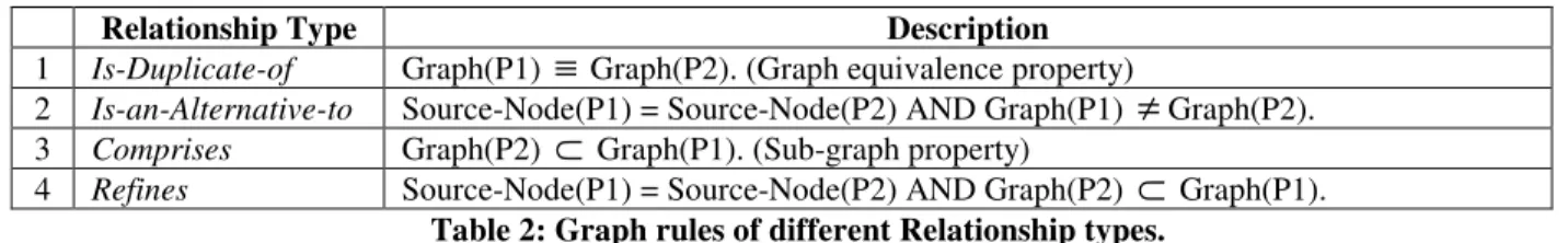
This model treats each pattern as a micro-architecture and defines the pattern as a topology of a set of design decisions. Using this model, different relationships are analyzed using graph properties. For example,
Patterns A and B are duplicates if Graph(A)
≡
graph(B),Pattern A comprises-of patterns B and C if Graph(B)
⊂
Graph(A) AND Graph(C)⊂
Graph(A).The rest of the paper is structured as follows: Section 2 provides the required background terminology. In section 3, we discuss briefly how a pattern is described as a DDTM. In section 4, we demonstrate the tactic topology model which is a kind of DDTM. Section 5 discusses related work, and section 6 concludes the paper suggesting some future directions.
2. Terminology
In this section, we review some software architecture terminology used in this paper.
of the software. Quality requirements specify the external constraints the software should meet. • Quality Attribute [2]: is a set of related quality
requirements.
• Design Decision [15]: is a strategy that is applied to solve a particular part of the problem.
• Tactic [2]: A tactic is a design decision that influences the control of a quality attribute parameter. For example, the Increase available resources design decision (upgrading 512 MB RAM to 1 GB RAM) controls (minimizes) the response time parameter.
• Implications/Side-effect [3, 25]: A design decision comes with many implications. For example, a design decision might introduce a need to make other decisions, create new requirements, or modify existing requirements; pose additional constraints to the environment. For example, the Increase available resources tactic which is an alternative to achieve Reduce response time quality requirement imposes side-effects like Increase in cost, Change in resource management (scheduling) policy etc.
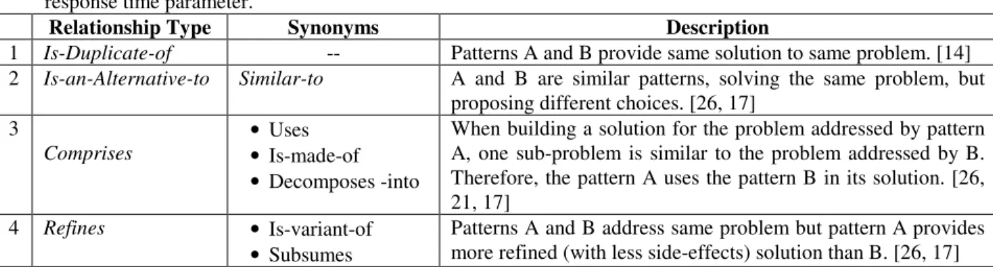
Relationship Type Synonyms Description
1 Is-Duplicate-of -- Patterns A and B provide same solution to same problem. [14] 2 Is-an-Alternative-to Similar-to A and B are similar patterns, solving the same problem, but
proposing different choices. [26, 17] 3
Comprises
• Uses • Is-made-of • Decomposes -into
When building a solution for the problem addressed by pattern A, one sub-problem is similar to the problem addressed by B. Therefore, the pattern A uses the pattern B in its solution. [26, 21, 17]
4 Refines • Is-variant-of • Subsumes
Patterns A and B address same problem but pattern A provides more refined (with less side-effects) solution than B. [26, 17]
Table 1: Description of different Relationship types. 3.
How to describe a pattern – the Design
Decision Topology Model (DDTM)
Analyzing the relationships for a given set of patterns can be considered as 3-step process:
• Analyze design decisions of the patterns. • Analyze the topology of the design decisions. • Analyze the relationships from the topologies.
3.1. Analyze design decisions of the patterns.
The key-information of a pattern is usually embedded in the essential sections of the pattern-form/template; Context, Problem, Solution, Consequences sections are considered to be essential sections [9, 5, 6]. Additional sections such as Implementation, Example etc often appropriate to provide meaningful guidance on where a pattern applies and how to apply it [6]. Hence we use the key-information provided in Problem, Solution, Consequences sections as clues to analyze design decisions.
3.2. Analyze topology of design decisions.
DDTM provides a structure to the design decisions of a pattern by explicitly representing the dependency among them. DDTM primarily provides rationale for existence of a particular design decision. This information is modeled as edges among design decisions in our graph model. An edge A B in DDTM means the side-effect of design decision A is resolved by design decision B.
The DDTM of a pattern can be viewed as a graph of design decisions. The Intent section specifies the primary design decision(s) of the pattern; they are modeled as source-nodes in the DDTM. Based on the implications of the current stage design decisions, the design decisions in the next stage are analyzed. For example, consider the Master-slave pattern [5]. The intent of Master-slave pattern is given as: the master component distributes the work to slave components to support parallel computation. It specifies Work partitioning as the primary design decision; and it is modeled as the source node in the DDTM of Master-slave pattern. One of the implications of Work partitioning design decision is the work distribution details need to be hidden from clients; hence Restrict communication paths design decision is used to overcome this implication. The continuation of the design process leads to an edge from Work partitioning to Restrict communication paths nodes in the DDTM of Master-slave pattern; the label on the edge represents the implication of Work partitioning design decision. Figure 1 shows a fragment of DDTM of Master-slave pattern.

![Table 5: Analysis of tactics for MVC pattern [5].](https://thumb-ap.123doks.com/thumbv2/123deta/8631367.449587/37.918.122.797.95.917/table-analysis-tactics-mvc-pattern.webp)